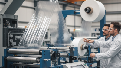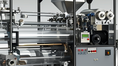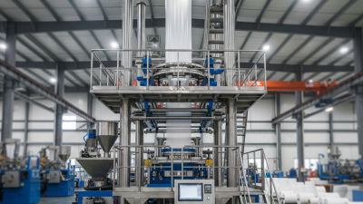
Choosing a Blown Film Extruder Machine in 2026 requires more than comparing prices and catalog photographs. Film manufacturers now face tighter quality expectations, changing material blends, energy concerns, and unpredictable production schedules. A machine that performs well in a supplier’s showroom may behave differently beside your existing cooling system, printing line, and experienced operators.
The right decision begins with the film application. Packaging film, agricultural film, stretch film, and recycled-content products demand different extrusion designs. Consider output stability, die size, cooling capacity, automatic thickness control, screw configuration, and compatible polymers. Small details matter. A fluctuating bubble can create visible gauge variation across a finished roll. Excessive motor noise may signal future maintenance concerns, not impressive power.
Look closely.
Reliable suppliers should provide documented test results, component brands, service procedures, and references from comparable factories. Request a material trial using your actual resin blend, additives, and target thickness. Ask how quickly technicians respond when production stops at midnight. Certifications and safety features also deserve careful review, but paperwork alone cannot prove long-term performance.
My experience with equipment evaluations has shown one uncomfortable truth: buyers often overvalue maximum output. Real production may depend more on stable running, simple cleaning, spare-parts availability, and operator training. Even experienced teams can overlook these practical costs. A lower purchase price can become expensive when film waste rises or troubleshooting takes several days.
This guide examines the technical, commercial, and operational factors behind a confident 2026 purchase. It will help you compare machines realistically, identify weak supplier claims, and choose equipment that supports dependable film production rather than impressive promises.
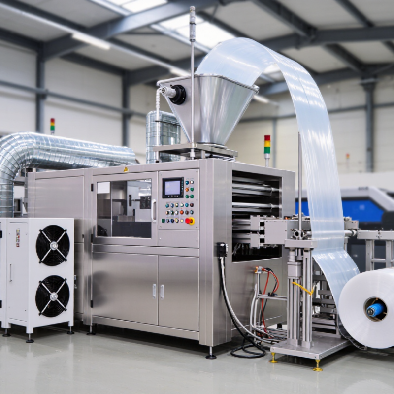
Choosing a blown film extruder in 2026 starts with the film, not the machine price. Define target thickness between 10 and 200 μm, then record the required web width. Write it down. A 10 μm liner needs different melt control from a 200 μm heavy-duty sheet. Specify whether width means layflat width or total tubular circumference. Resin type, additives, layer structure, and sealing temperature also affect the choice. Do not treat nominal thickness as the whole specification.
Ask suppliers for stable output at your actual gauge, not only their maximum capacity. For thin film, examine gauge variation, cooling performance, die adjustment, and bubble stability. For thicker film, check motor torque, melt pressure, and winding tension. Measure web width after cooling, because neck-in can reduce usable width. A 1,600 mm die may not deliver a 1,600 mm finished web. That detail is easy to miss.
During evaluation, run your own resin at several thicknesses and widths. Keep samples from the center and both edges. Test thickness, tensile strength, haze, seal strength, and roll appearance. I have seen attractive trial data fail during overnight production. It happens. Confirm whether the machine holds width when speed changes. Review maintenance access, operator training, and spare-part availability. A lower price can become expensive when adjustments are slow or inconsistent.
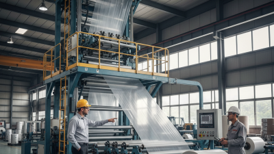
Polymer selection should guide the extruder, not the other way around. LDPE melts easily and offers strong bubble stability. It suits flexible films with good clarity and sealing performance. LLDPE improves puncture resistance, but it can demand higher torque and careful cooling. HDPE creates stiffer films and needs stronger melt control. Its narrower processing window can expose weak machine settings.
Die design must match the polymer and target thickness. A smaller die gap can support thinner, more uniform film. However, an excessively narrow gap may increase pressure and restrict output. Wider gaps help heavy films, but they can amplify gauge variation. I have seen stable machines produce uneven rolls after a small die adjustment. Test data matters more than attractive specifications. Film width, output rate, cooling capacity, and screw design should be checked together.
Tips: Ask for trial data using your actual resin grade. Record melt temperature, die pressure, frost-line height, and thickness variation. Keep a small allowance for future materials. Your ideal setting may change. A machine optimized for LLDPE today may struggle with HDPE tomorrow. Review the die lip design, automatic gauge control, and cleaning access before purchasing. These details affect daily reliability more than a polished sales sheet.
When choosing a blown film extruder in 2026, begin with real film demand, not the machine’s headline capacity. A listed output of 100 kg/h may change with resin type, film thickness, die gap, and cooling efficiency. Ask for tested output using materials similar to yours. A number without conditions is weak evidence.
Screw L/D ratio deserves careful attention. A longer screw can improve melting, mixing, and pressure stability. However, it may increase residence time and heat exposure. That matters for temperature-sensitive polymers. A shorter screw may suit simple products, but it can limit flexibility. Bigger is not always better. Match the ratio to your materials, layer structure, and expected production speed.
Calculate required capacity from actual orders, not optimistic forecasts. For example, 500 tonnes yearly across two shifts requires different equipment from occasional short runs. Include startup waste, roll changes, maintenance, and seasonal demand. A 20% capacity buffer often protects delivery schedules, but excessive capacity can create poor utilization and higher energy costs. I have seen neat spreadsheets mislead buyers because they ignored downtime. Request stable output data, melt temperature records, film thickness variation, and energy use. Then compare those figures with your operators’ skill level and available floor space. The best machine is the one that reaches your target consistently, not the one with the largest kg/h label.
How to Choose a Blown Film Extruder Machine in 2026?
A reliable blown film extruder should control thickness, not merely produce a stable bubble. Set a practical target of ±5% thickness variation across the web. This requires steady melt pressure, accurate temperature zones, and responsive air-ring control. Automatic gauge feedback can adjust die output when the film becomes uneven. Watch the bubble closely. A slight flutter may become a serious thickness problem after winding.
Use ASTM D374 as a disciplined reference for thickness measurement, but verify its applicability to your film structure. The standard primarily addresses solid electrical insulation materials. Your quality team should define conditioning, specimen preparation, instrument accuracy, and measurement points before testing. Measure across the film width and along the production direction. Record results, not impressions. In practice, a calibrated micrometer and consistent contact pressure can reveal errors that online sensors miss.
Tips: Ask for trial data from the machine supplier. Request thickness maps, melt-pressure records, and samples from different production speeds. Check whether the control system stores alarms and correction history. Inspect the die lips after a long run; small deposits can create repeating stripes. Do not trust one perfect sample. I have seen good results disappear when resin moisture, cooling air, or line speed changed. Leave room for adjustment, because a ±5% target may prove difficult with thin films, recycled content, or unstable materials.
| Selection and Quality Dimension | Recommended Target or Range | Example Calculation or Acceptance Limit | What to Check Before Purchase | Quality-Control Relevance |
|---|---|---|---|---|
| Thickness control objective | Maximum thickness variation: ±5% from nominal thickness | For 50 μm film: acceptable range = 47.5–52.5 μm | Request a documented thickness-control capability test using the intended resin and film structure | Defines the primary acceptance criterion for stable film production |
| ASTM D374 measurement basis | Use a calibrated thickness-measurement procedure appropriate for the film material and gauge | Record gauge type, applied pressure, calibration status, sampling location, and measured value | Confirm that the supplier can provide a written test procedure aligned with the applicable ASTM D374 method and product specification | Improves repeatability and prevents machine settings from being judged with inconsistent measurement practices |
| Nominal film thickness | Typical flexible-film operating window: approximately 20–150 μm, depending on resin and application | For 100 μm film: acceptable range = 95–105 μm at ±5% | Verify die design, screw configuration, cooling capacity, and haul-off speed for the required gauge range | A machine optimized for thick film may not provide stable output at thin gauges |
| Thickness sampling plan | Measure at evenly distributed positions across the web and along the production direction | A practical internal check may use at least 10 cross-web positions and repeated machine-direction samples | Check whether the control system supports trend recording, alarm limits, and traceable sample identification | Detects both cross-web profile errors and changes caused by temperature or output drift |
| Automatic die-gap control | Select a die with adjustable lip-gap control and closed-loop profile correction where ±5% variation is critical | The control system should identify local high and low thickness zones and apply corrective adjustments | Review sensor resolution, correction response time, heating-zone layout, and manual override functions | Reduces cross-web thickness deviations caused by die-lip temperature and gap differences |
| Melt-temperature stability | Maintain a stable melt-temperature profile suitable for the selected polymer; avoid unnecessary temperature swings | Specify a documented process window rather than relying only on the barrel-set temperature | Confirm melt-temperature measurement, independent zone control, alarms, and data logging | Temperature fluctuations change melt viscosity and can create machine-direction gauge variation |
| Extruder screw design | Select a screw geometry matched to the polymer family, throughput, additives, and required film structure | Use separate process validation for polyethylene, polypropylene, barrier structures, and recycled-content blends | Check screw diameter, L/D ratio, compression profile, mixing section, and material residence time | Correct screw design supports uniform melting and stable pressure at the die |
| Melt-pressure stability | Pressure should remain steady during a qualified production run without unexplained pulsation | Set an internal alarm limit based on the validated process; investigate recurring pressure oscillation before release | Verify pressure transducer location, display resolution, alarm history, and screen-pack or filter-change procedure | Pressure instability can directly produce periodic thickness changes in the film |
| Air-ring cooling | Use uniform, adjustable cooling around the bubble with stable airflow and temperature | Confirm that cooling settings remain repeatable during the full production speed range | Inspect air-ring adjustment, airflow balance, cooling-air filtration, and bubble-cage stability | Uneven cooling changes frost-line height, bubble stability, and cross-web gauge uniformity |
| Haul-off and nip control | Use a synchronized haul-off with low speed fluctuation and controlled nip pressure | Validate line speed, film width, and thickness at the intended production rate | Check drive synchronization, speed feedback, nip alignment, and tension-control capability | Speed changes affect drawdown and therefore machine-direction thickness |
| Output matching | Choose rated output with sufficient operating margin instead of running continuously at maximum capacity | Select a practical operating point that leaves room for start-up, material changes, and process fluctuations | Compare required kilograms per hour with screw capacity, motor power, cooling capacity, and die throughput | Operating too close to the machine limit can reduce pressure and thickness stability |
| Data logging and traceability | Record thickness, melt pressure, melt temperature, line speed, output, cooling settings, and alarms | Link each quality result to a production lot, operator, recipe, and measurement instrument | Request exportable data, user access levels, audit trails, and automatic out-of-limit notifications | Supports root-cause analysis when thickness exceeds the ±5% target |
| Final machine acceptance test | Run the intended film structure at the specified nominal gauge and production speed | Pass when the defined sample set remains within 95–105% of nominal thickness for a 100 μm specification | Include resin grade, additives, die configuration, line speed, cooling conditions, sampling plan, and calibrated equipment | Provides objective evidence that the selected machine can meet the required thickness-control target |
A safe extruder should provide clear CE conformity documentation, not just a CE sticker. Ask for the declaration, electrical drawings, and safety test records. ISO 12100 should guide the machine’s risk assessment, including heated surfaces, rotating screws, nip points, and emergency stops.
During a factory inspection, check whether guards close properly and whether operators can reach danger zones. Small details matter.
Energy efficiency needs measurable evidence. Request operating data in kWh/kg at your intended output, resin, film width, and thickness.
A useful benchmark may range from 0.35 to 0.70 kWh/kg, but cooling systems and recycled content can change results.
One quoted figure may look excellent. It may not match your production floor. I have seen estimates become less attractive after startup losses and unstable output were included.
Tips: Compare a logged production trial, not a brochure claim. Record power consumption, kilograms produced, scrap rate, and running hours. Test your actual resin blend when possible. Check whether the meter includes heaters, drives, air cooling, and auxiliary equipment. Ask how often sensors require calibration. Also, leave room for human error. Operators need practical training, readable alarms, and simple maintenance access. A machine can meet formal requirements yet remain difficult to use safely.